Author Topic: Heater control with arduino and remote control mains sockets  (Read 8823 times)

nikki

  • Administrator
  • Newbie
  • *****
  • Posts: 34
Heater control with arduino and remote control mains sockets
« on: November 15, 2013, 05:36:54 PM »
I live in a rented attic flat with 2 oil-filled radiator heaters and substantially less in the way of insulation.

Getting a balance between tolerable heat coolth and just pumping energy straight out of the roof is a tricky art, but this year I've decided to add some science...

The aim is to be a bit cleverer with thermostat control and hopefully also to add in a remote control so I can switch the heating on as I make my way back home after being elsewhere. There's going to be a lot of learning with this one, but isn't there always?!

So far I've rigged up some Maplin remote control sockets to an Arduino nano.

The sockets are conveniently on offer at the moment and someone has conveniently decoded the transmitter signals and provided some code for use with something like this. So far so convenient.

This has made it really very easy to rig up circuit and code that turns on a heater (manually set to max) for 10 minutes if a TMP35 sensor thinks the temperature has fallen below 9 degrees centigrade.

Code: [Select]
// See http://www.fanjita.org/serendipity/archives/53-Interfacing-with-radio-controlled-mains-sockets-part-2.html

/* Sensor test sketch
 for more information see http://www.ladyada.net/make/logshield/lighttemp.html
 */

unsigned long start=0;


#define aref_voltage 3.3 // we tie 3.3V to ARef and measure it with a multimeter!
//TMP36 Pin Variables
int tempPin = 1; //the analog pin the TMP36's Vout (sense) pin is connected to
//the resolution is 10 mV / degree centigrade with a
//500 mV offset to allow for negative temperatures
int tempReading; // the analog reading from the sensor
float temperatureC;

#define PAYLOAD_SIZE 48
#define GND_PIN A2
#define DATA_PIN A3
#define VCC_PIN A4

#define LED_PIN 13

#define PULSE_WIDTH_SMALL 500

// Button ID (payload1) values. There are 4 values for 4 channels, organised as
// ch1_btn1, ch1_btn2, ch1_btn3, ch1_btn4, ch2_btn1, etc.
long buttons[] = {
  859124533L,
  861090613L,
  892547893L,
  1395864373L,
  859124563L,
  861090643L,
  892547923L,
  1395864403L,
  859125043L,
  861091123L,
  892548403L,
  1395864883L,
  859132723L,
  861098803L,
  892556083L,
  1395872563L
};

void setup()
{
  // Plug the TX module into A3-A5, with the antenna pin hanging off the end of the header.
  pinMode(GND_PIN, OUTPUT);
  pinMode(DATA_PIN, OUTPUT);
  pinMode(VCC_PIN, OUTPUT);
  pinMode(LED_PIN, OUTPUT);
  Serial.begin(115200);

  // If you want to set the aref to something other than 5v
  analogReference(EXTERNAL);


  start = millis();

}

void sendData(long payload1, long payload2)
{
  // Turn on the radio. A3=GND, A5=Vcc, A4=data)
  digitalWrite(GND_PIN, LOW);
  digitalWrite(VCC_PIN, HIGH);
  digitalWrite(DATA_PIN, HIGH);
  digitalWrite(13, HIGH);
  // Send a preamble of 13 ms low pulse
  digitalWrite(DATA_PIN, LOW);
  for (int ii = 0; ii < 26; ii++)
  {
    delayMicroseconds(PULSE_WIDTH_SMALL);
  }
  digitalWrite(13, LOW);
  // send sync pulse : high for 0.5 ms
  digitalWrite(DATA_PIN, HIGH);
  delayMicroseconds(PULSE_WIDTH_SMALL);
  digitalWrite(DATA_PIN, LOW);
  // Now send the digits.
  // We send a 1 as a state change for 1.5ms, and a 0 as a state change for 0.5ms
  long mask = 1;
  char state = HIGH;
  long payload = payload1;
  for (int jj = 0; jj < PAYLOAD_SIZE; jj++)
  {
    if (jj == 32)
    {
      payload = payload2;
      mask = 1;
    }
    char bit = (payload & mask) ? 1 : 0;
    mask <<= 1;
    state = !state;
    digitalWrite(DATA_PIN, state);
    delayMicroseconds(PULSE_WIDTH_SMALL);
    if (bit)
    {
      delayMicroseconds(PULSE_WIDTH_SMALL);
      delayMicroseconds(PULSE_WIDTH_SMALL);
    }
  }
}

void simulate_button(int channel, int button, int on)
{
  long payload1 = buttons[(channel - 1) * 4 + (button - 1)];
  long payload2 = on? 13107L : 21299L;
  //  Serial.println(payload1);
  //  Serial.println(payload2);

  // Send the data 6 times
  for (int ii = 0; ii < 6; ii++)
  {
    sendData(payload1, payload2);
  }
  // turn off the radio
  digitalWrite(VCC_PIN, LOW);
}

void loop()
{

  Serial.print(millis());
  Serial.print(",");
  Serial.print(millis() - start);
  Serial.print(",");
  getTemp();

  Serial.print(temperatureC);
  Serial.print(",");

  if    (millis() - start > 600000) {

    if (temperatureC < 9){
      simulate_button(1, 3, 1);
      Serial.print("ON");
      Serial.print(",");
      delay(600000);
    }

    else {
      simulate_button(1, 3, 0);
      Serial.print("OFF");
      Serial.print(",");
    }
    start = millis();
  }
  else {
    Serial.print("MONITORING");

  }
  delay(120000);
  Serial.println("");

}//end loop

float getTemp(){

  tempReading = analogRead(tempPin);
  // converting that reading to voltage, which is based off the reference voltage
  float voltage = tempReading * aref_voltage;
  voltage /= 1024.0;
  temperatureC = (voltage - 0.5) * 100 ; //converting from 10 mv per degree with 500 mV offset
  return temperatureC ;

}


This is giving me a csv of some timing information, recorded temperature and whether the system is turning the heater on, off, or just giving an intermediate temperature reading.

Quote
millis, millis since last switch action, temp, action
121000,121000,12.52,MONITORING
242001,242002,12.84,MONITORING
363003,363003,13.49,MONITORING
484004,484005,12.52,MONITORING
605006,605006,12.52,OFF,
726380,120000,12.52,MONITORING
847382,241001,13.49,MONITORING
968384,362003,13.49,MONITORING
1089385,483004,13.49,MONITORING
1210387,604006,13.81,OFF,
1331761,120001,12.84,MONITORING
1452763,241002,13.16,MONITORING
1573765,362004,12.52,MONITORING
1694766,483006,12.20,MONITORING
1815768,604007,12.52,OFF,
1937141,120000,11.55,MONITORING
2058143,241001,11.87,MONITORING
2179145,362003,11.87,MONITORING
2300146,483005,11.55,MONITORING
2421148,604006,11.55,OFF,


I've no idea how accurate the temperature reading is, but it's been interesting watching the gradual decrease throughout the day.

Next steps are to set different target temperatures for different times of day (I think my options are to either either get a Real Time Clock breakout board, use one of the GPS units I have lying around, or add an ethernet shield), and to add in some remote remote control using my phone, either with an ethernet shield or one of the cellular shields I've acquired and have been wanting to learn how to use...

Has anyone got any links/experience they can point me towards that might be useful?
« Last Edit: November 15, 2013, 05:38:35 PM by nikki »

Maker of Things

  • Jr. Member
  • **
  • Posts: 57
  • @Maker_of_Things
Re: Heater control with arduino and remote control mains sockets
« Reply #1 on: November 15, 2013, 11:09:21 PM »
Impressed!


Not being into electronics and 'bits of code' I would have used a programmable wireless CH room thermostat connected to the heater.
Probably much more expensive though,
« Last Edit: November 15, 2013, 11:26:11 PM by Maker of Things »
If it ain't broke, you're not hitting it hard enough!

nikki

  • Administrator
  • Newbie
  • *****
  • Posts: 34
Re: Heater control with arduino and remote control mains sockets
« Reply #2 on: December 01, 2013, 08:26:44 PM »
Right, I think I've arrived at a stable set-up, so thought I'd report back...

Here's the brains:


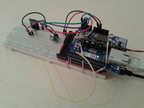
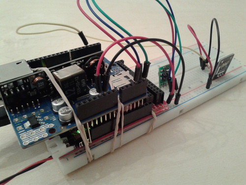
It's an Arduino Mega (actually a Seeedstudios version) with an ethernet shield, a temperature sensor, a radio transmitter and a couple of vital rubber bands :)

I started off using an Arduino Uno, but before long I was getting some really erratic behaviour that had me scratching my head for a few days. Turns out it was running out of memory, but the switch to a Mega has solved that  ...for now  ;D

I also switched to a DS18B20 temperature (from the TMP35) when I discovered I had one lying around. This gave me readings that agreed a lot closer with the weather station control panel a friend has lent me for calibration purposes.


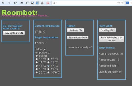
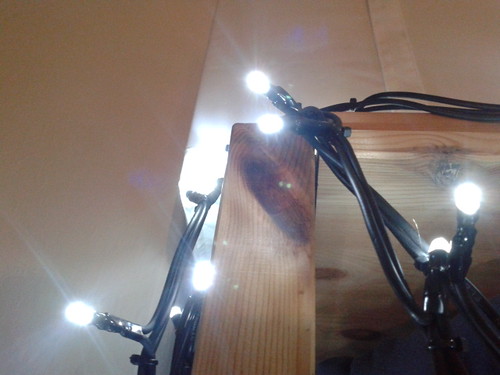
It's all controlled from a web interface that shows a page stored on the SD card in the ethernet shield. This means I can access it from home or when I'm away. As well as the remote-controlled fairy lights (originally a handy indicator to see if I'd got things working, but now I can't imagine how I lived without them - they're immensely satisfying!), I'm currently using a thermostat style system to switch an oil-filled radiator on and off and also switching a lamp on and off at random intervals between set start and finish hours.

Some useful things in case you're thinking of rolling your own:

The RF codes for the remote sockets

A tutorial for using the ethernet shield to make a webserver (this is really detailed and builds up to the grand finale over several stages.

Arduino libraries:
MemoryFree https://github.com/maniacbug/MemoryFree
OneWire http://www.hacktronics.com/code/OneWire.zip
DallasTemperature http://www.hacktronics.com/code/DallasTemperature.zip (tutorial)
EthernetUdp  (example)

The starting electronics web server tutorial had example code for the buttons and updatable text, and this snippet gave a base to sort out the radio buttons used for the thermostat settings.


A couple of people have asked me about cost, so let's see how it shapes up...

Arduino Mega ~£40 for a 'proper' one, I had a Seedstudio version already, and have ordered one of these to try (~£12.50)
Ethernet shield Proper ~£30 Deal Extreme on order to try ~£6
Maplin remote controlled plugs Currently (no pun intended) 3 for £15
Temperature sensor I found one of these ~£1.70 lying around, will probably get a few from Tayda if I decide to do the other room too.
RF transmitter  one of these ~£4
breadboard £few
Ethernet and USB cables £no idea, you've probably got one in a drawer somewhere?

4.7k resistor and some hook-up wire £pence

Edited to add: Power adaptor soo you don't have to run the set-up off a computer (think it was about a fiver off amazon) and a SD card (similar)


So, between ~£100 and ~£40 depending on how those cheap Deal Extreme arduino clones shape up. Easily expandable to more appliances, and adaptable to control different types of output, I reckon that's very much worth it for my context! (Especially since I already had everything except for the RF transmitter and the sockets!)


I'm going to let this run for a few days and get the feel for how it's behaving and whether there are any bugs that need sorting out. Next steps might be doing automated changes via Tasker and I'll have a think about panic buttons for those times when you've left the house but have a gnawing feeling you've left the hair straighteners / soldering iron on...

In the meantime:


Lights on, lights off, lights on, lights off...
« Last Edit: December 01, 2013, 08:31:04 PM by nikki »